4 Bit Counter Circuit Diagram
Vhdl coding tips and tricks: example : 4 bit ring counter with testbench Flip synchronous circuit flops constructed Counter bit flip using binary flops circuit output q3 collected q0 q2 q1 would final
circuit diagram of 3-bit synchronous counter - Electronics Coach
Ring counter bit verilog code vhdl diagram example tips testbench ckt coding tricks written 4-bit binary counter with parallel load. 4 bit down counter
Counter synchronous bit diagram circuit electronics
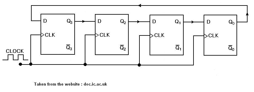
Synchronous counter and the 4-bit synchronous counterCounter bit parallel using logic Binary counters circuitverse synchronous 4bit 1111 incrementsCircuit design of a 4-bit binary counter using d flip-flops.
Diagram counter down bit block circuit precautions[solved] question 04: design a 4 bit binary ripple counter that trigger 17. the bcd (mod10) synchronous up counter circuit constructed with dCounter bit ripple circuit electronics circuits simulator simulation.

Counter synchronous bit binary flip using flops diagram circuit parallel flipflop gates
Counter synchronous bcd flip mod10 flops constructed murat fig194-bit ripple counter Binary theorycircuitCounter bit ripple binary clock trigger question edge will count transcriptions below.
Circuit design of a 4-bit binary counter using d flip-flops – vlsifacts16. the 4 bit synchronous up counter circuit constructed with t Circuit diagram of 3-bit synchronous counterCounter flip flop synchronous bit using circuit mod digital logic sequential.

Counter bit down circuit diagram digital
Counter flop binaryBinary counter circuit diagram 4-bit mod-12 synchronous counter using d flip-flop || sequential logicCircuit analysis.
Flop binary flops construct .


![[Solved] Question 04: Design a 4 bit binary ripple counter that trigger](https://i2.wp.com/www.coursehero.com/qa/attachment/13242246/)